
Overview
The Prototype can still be built, although its digital relay timers and solenoid valves are not robust enough to be used continuously for weeks to months. It was also not intended for use with blended oxygen. It was built primarily as a proof of concept. Unless you need a Field Ventilator quickly; for a very short time; and don’t need it to deliver blended oxygen/air, we highly recommend building the Rev 2 Unit.
Depending on the frequency of breaths being delivered to patients, it is possible the field ventilator could see 1 million cycles within 20 days. The revised design (Rev 2) is anticipated to have a service life of at least 20 million respiratory cycles due to use of solid state relays and upgraded valve solenoids. Rev2 was also designed with oxygen cleaned components, to incorporate blended oxygen at varying FiO2 percentages from room air to 100% O2. Specially designed, oxygen cleaned solenoid valves were manufactured by Spartan Scientific just for this application.
This section describes the Prototype, which had the following modes of operation:
1 to 1 Inhale/Exhale Ratio
This field ventilator was initially built to supply respiratory support to 8-12 patients on a 1:1 Inhale/Exhale cycle (I:E ratio). Essentially, this is BiPAP mode. What determined whether 8 or 12 patients could be supported was the flow rate demands of the patients (ie their individual breath size or tidal volume). The air pump we selected can supply room air to 8 patients at 6+ Liters per minute. If less flow is needed, more patients can be supported. The original unit was tested at 2.5 Liters per minute of flow to 12 patient ventilator ports.. The field ventilator was designed to allow variable flow control on each patient port, with pressure relief to 45cm H2O to guard against barotrauma. Delivering air flow from a pump to 8 to 12 patients on a 1:1 I:E ratio is accomplished by flow diverter valves controlled by solenoids on the signal of a programmable digital relay timer. Flow was originally diverted back and forth between two ventilation manifolds with 4-6 patients connected to each. During the inhalation cycle of one group of 4-6 patients, air is supplied by the pump to their manifold. At that time, the other group of 4-6 patients is exhaling. Consequently, air flow from the pump is diverted away from that manifold. It is important to prevent the pump’s air flow from being shuttered (or “deadheaded”) in order to prevent compressive heating and premature failure of the pump.
1 to 2 Inhale/Exhale Ratio
In Acute Respiratory Distress Syndrome situations like that posed by the COVID-19 virus, it was proposed early in the pandemic that a 1:2 I:E ratio may be a more desirable respiratory rhythm. This presents a greater challenge for a ventilator because the amount of inhale and exhale time is different. We created a second version of the field ventilator to allow this more favorable I:E ratio, but it meant the addition of a second digital relay timer; a third patient manifold (capable of supporting respiration to an additional 4-6 patients); two additional solenoid valves (one normally open and one normally closed); and additional tubing and wiring. The essential function of the unit is the same. Namely, an air pump supplies continuous flow that is being divided between groups of patients attached to a common manifold. But the timer logic and valve open/close times are more difficult to synchronize (the digital relay timers used in Rev1 are not sophisticated enough to control multiple valves operating on different timing cycles). We have provided explanations of the modifications needed to deploy the field ventilator as a 1:2 respiratory device using simplified digital relay timers.
According to data we received from the University of California San Francisco on April 2, 2020, some COVID-19 patients are likely to fare better if they’re put on CPAP before they begin developing respiratory distress. Both the Rev1 and Rev2 Field Ventilators are capable of being operated in CPAP mode. Rev1 does this by simply stopping the timers and switching two hoses. Watch the two minute video for a demonstration.
WARNING: DO NOT SUPPLY OXYGEN INTO THE PUMP’S AIR INTAKE. EXPLOSION RISK!
It is generally desirable to mix room air being supplied at high flow by the ventilator pump with 100% oxygen in varying proportions (i.e. FiO2). The Field ventilator can be configured to allow 100% oxygen to be mixed into the patient ventilator air ports. This requires insertion of inline check valves on both the main supply from the pump; and the Oxygen supply tubing. An oxygen pressure regulator must be installed in the oxygen line upstream of a one-way valve to reduce delivery pressure to that of the air pump system. The oxygen is then spliced into the main pump supply, such that mixing of O2 and room air occurs before flow branches to the patient manifolds. In order to use oxygen with the field ventilator, the solenoid valves and check valves must be oxygen cleaned to remove oils from the manufacturing process. Otherwise, there is an additional risk of combustion. If oxygen will be used, we recommend building Rev2.
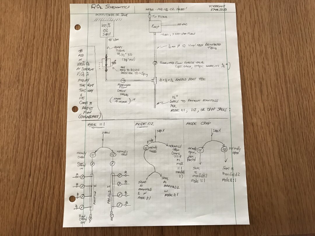
To add pure O2 to the vent, follow these steps (see schematic diagram below):
- Add a check valve to the main pump supply line near (but upstream of) the first tee. This check valve must require no more than 1-2 psi cracking pressure and be able to withstand at least 50 psi max pressure. Commercially available valves are available that have 1psi crack and 150psi rated pressure. These will be fine. Use 1/2″ fittings that connect to 3/8″ barbed tubing adapters.
- From the O2 supply line from the wall or tanks, you’ll need 45LPM to be available (either with a triplex providing 45 LPM out one port; or three individual 15 LPM lines teed into one for a total of 45 LPM). If the pressure of your O2 supply line is not regulated down to approximately 5 psig (from 50 psi at the supply), you will need to do that. You will still need to have up to 45 LPM available at the point of teeing into the field ventilator tubing, so multiple wall lines could be needed (e.g. three of them flowing 15 LPM at 5 psig would be fine).
- Add another check valve (same rating as the one specified in step 1) to the 45LPM pure O2 supply. These check valves help prevent back flow in the lines. As stated above, all valves that will be exposed to oxygen at concentrations greater than room air need to be oxygen cleaned to remove oils. Again, because of this requirement, if you need supplemental oxygen to be blended with room air, build the Rev2 model.
- Splice the O2 line into a tee fitting. You’ll also need tubing adapters to get from the O2 manifold up to the 5/8”x1/2” ID vinyl mesh reinforced tubing used for the other air supply lines. The other 2 tubes coming into the tee are the pump supply line downstream of the check valve; and what is now going to be the main supply line to the patient manifolds.
- Refer to the different modes of setup (1:1, 1:2, and CPAP) and connect the main supply line from Step 4 as before (again, see schematic diagram below).
Advantages to added O2:
More patients can potentially be ventilated due to the higher combined flows; however doing so will require manifold extensions to be added to the 4-patient manifolds specified in the design; or flow control will need to be present on the 4-patient manifolds. Control of FiO2 within the broadest range will also require addition of a bypass line on the air pump supply tubing, upstream of the check valve in that line. This is illustrated in the Rev2 build photos. Flows and mixing ratios will need to be measured empirically for all patient ports, regardless of respiratory mode.
If the pump fails and cannot be replaced for some reason (refer to pump failsafe video), 100% O2 could be given and the timing and solenoid switching valves will continue to deliver O2 to patients at 100%. The system will continue to deliver O2 to patients at 100% ACCORDING TO THE PROGRAMMED TIMER INTERVAL prescribed by the physician.
Download the FiO2_Manifold_Flow.xlsx Excel spreadsheet
Legal Disclaimer
The content on this website is being released in this manner to maximize the potential public benefit during this urgent need for measures to respond to the COVID-19 crisis, including promoting potential ventilator manufacturing methods.
The content has not been reviewed or approved by the U.S. Food and Drug Administration (FDA). Interested readers are encouraged to contact the FDA and review available FDA materials, including their guidance on ventilators as well as the Department of Health and Human Services (DHHS) declaration of liability immunity for medical countermeasures against COVID-19.
PLEASE NOTE: The content has not been peer reviewed. The Authors make no representations or warranties of any kind (express or implied) relating to accuracy, safety, usefulness, usability, marketability, performance, or otherwise of the content released here. The Authors disclaim all express and implied warranties of merchantability and fitness of the content for a particular purpose, and disclaims all express and implied warranties regarding non-infringement of any patent, copyright, trademark, or other rights of third parties in the content or use of the content, or in the making, using, or selling products or services by any person or entity.
People or entities attempting to use the content in any way, including creating products or offering services, assume all risk and responsibility related to those uses, including all legal and regulatory compliance, safety, efficacy, performance, design, marketability, title, and quality. The Authors assume no liability related to the actions of third parties and in respect of any infringement of any patent, copyright, or other right of third parties.
The content has not been used in testing with humans at this time.
The Authors’ names and logos are trademarks or other exclusive property of the Authors. Readers of the content shall not use the name or logo of any Author in any way for publicity, advertising, or other commercial purposes, including linked to the reader’s products or services. Readers of the content shall not make statements or representations that, in Author’s sole judgment, deliberately or inadvertently claim, suggest, or give the appearance or impression of a relationship with or endorsement by that Author.
The Authors are proud of their affiliation with the University of Colorado as alumni and, in the case of Dr. Thomas Greany, as a professor at the Anschutz Medical Campus. The Authors express their appreciation to the University of Colorado for its support of this project.